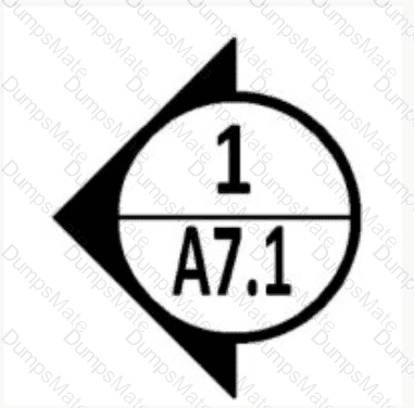
The symbol shown in the image is a circular tag with an arrow pointing to the left, divided into two halves. The top half contains the number "1," and the bottom half contains the designation "A7.1." This type of symbol is commonly used in architectural and interior design drawings to reference specific views or drawings within a set of construction documents. To determine what type of tag this symbol represents, we need to analyze its format and context based on standard drafting conventions, as outlined in NCIDQ Interior Design Fundamentals.
Step 1: Analyze the Symbol's Format
Shape and Arrow: The symbol is a circle with an arrow pointing to the left. In architectural drawings, such symbols are typically used to indicate a reference to another drawing or view. The arrow suggests the direction of the view or the location of the referenced element.
Numbering: The top half of the circle contains the number "1," which usually indicates thespecific view or cut being referenced (e.g., the first section or detail). The bottom half contains "A7.1," which likely refers to the sheet number (A7.1) where the referenced drawing can be found.
Context: The symbol is likely placed on a floor plan or another drawing to direct the viewer to a related drawing, such as a section, elevation, or detail.
Step 2: Evaluate Each Option Based on Drafting Standards
Option A: PlanA plan tag typically does not use a circular symbol with an arrow. Floor plans are usually labeled directly on the drawing (e.g., "First Floor Plan") and do not require a reference tag like this. Instead, a plan tag might be a simple label or title block. The symbol in the image is more specific to a cross-reference, not a plan itself, so Option A is not correct.
Option B: DetailA detail tag is used to reference a detailed drawing of a specific element, such as a close-up of a construction joint or a custom millwork piece. Detail tags often use a circular symbol with a number and sheet reference, similar to the one shown. For example, a detail tag might read "1/A7.1," meaning "Detail 1 on Sheet A7.1." However, detail tags typically do not include an arrow indicating direction, as details are not directional views but rather magnified views of a specific area. The presence of the arrow in this symbol suggests a directional view, making Option B less likely.
Option C: SectionA section tag is used to indicate where a vertical cut (section) is taken through a building or space, showing the interior structure or details. Section tags are commonly represented by a circular symbol with an arrow, where the arrow indicates the direction of the view (i.e., the direction the viewer is looking when the section is drawn). The circle is often divided, with the top half showing the section number (e.g., "1") and the bottom half showing the sheet number where the section drawing can be found (e.g., "A7.1"). The symbol in the image matches this format exactly: the arrow points to the left, indicating the direction of the section view, and the "1/A7.1" format aligns with standard section tagging conventions. This makes Option C the most likely answer.
Option D: ElevationAn elevation tag is used to reference an elevation drawing, which shows a vertical view of a wall or facade. Elevation tags may also use a circular symbol with a number and sheet reference, but they typically do not include an arrow, as elevations are not directional in the same way sections are (elevations show a flat view of a wall, not a cut through the building). Some elevation tags might include an arrow to indicate the wall being viewed, but this is less common than with section tags. The symbol in the image, with its prominent arrow, is more characteristic of a section tag than an elevation tag, making Option D less likely.
Step 3: Conclusion Based on Drafting Standards
The symbol’s format—a circle with an arrow, divided into two halves, with a number (1) and a sheet reference (A7.1)—is a standard representation of a section tag in architectural and interior design drawings. The arrow indicates the direction of the section view, and the "1/A7.1" format tells the viewer to look at Section 1 on Sheet A7.1. This aligns with NCIDQ guidelines and standard drafting practices, where section tags are used to reference vertical cuts through a building or space.
While a detail tag might use a similar format, the presence of the arrow strongly suggests a directional view, which is characteristic of a section rather than a detail. An elevation tag is also possible but less likely due to the arrow, and a plan tag does not fit the symbol’s purpose.
Therefore, the correct answer isC: Section.
Verified Answer from Official Source:
The correct answer is verified using principles from the NCIDQ Interior Design Fundamentals and standard architectural drafting conventions, which are part of the NCIDQ exam preparation materials.
Exact Extract:
From the NCIDQ IDFX Reference Manual (a common resource for NCIDQ candidates):
"Section tags are represented by a circular symbol with an arrow indicating the direction of the view. The circle is typically divided, with the top half showing the section number and the bottom half showing the sheet number where the section drawing is located (e.g., '1/A7.1' means Section 1 on Sheet A7.1)."
The NCIDQ guidelines specify that a section tag uses a circular symbol with an arrow to indicate the direction of the section view, with the section number and sheet number provided within the circle. The symbol in the image matches this description: the arrow points to the left, indicating the direction of the section, and the "1/A7.1" format directs the viewer to Section 1 on Sheet A7.1. This is a standard convention in architectural and interior design drawings, ensuring clarity in referencing related drawings. Options A, B, and D do not align with this specific format as closely as Option C does, as they either lack the directional arrow (for plans and details) or are less commonly associated with an arrow (for elevations).
Objectives:
Understand the use of reference tags in architectural and interior design drawings.
Identify the purpose and format of section tags in construction documents.
Differentiate between section, detail, elevation, and plan tags based on their symbols and context.
[References:, NCIDQ IDFX Reference Manual (specific section on drafting standards and reference tags)., NCIDQ Practice Exam Questions (similar questions often test knowledge of drafting symbols and tags)., Architectural Graphic Standards (a widely used reference for drafting conventions, often cited in NCIDQ materials)., , , ]